Seeburg Wall-O-Matic: Counting pulses on ESP 8266

The ESP8266 is widely used in IoT applications. I have programmed a multitude of different sensors with it. And I almost found it’s limits – counting real-time pulse from a Seeburg Wall-O-Matic .
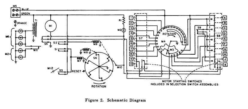
I like electro-mechanical devices and I am in awe each time I realize what engineers accomplished with cog-wheels, relays, levers and contacts. Think about the rotary telephone and it’s purely mechanically driven connection environment, teletype writers or early jukeboxes like the Wurlitzer 24 I restored. Finally I was able to add a Seeburg 3W1 Wall-O-Matic to my collection. A device from the 1950s that used to be installed in restaurants and bars and that allowed patrons to remotely select songs which would then be played from the jukebox.
Again – this is a purely electro mechanical devices. Drop in a nickel, push the select buttons and a rotating switch blade (contact arm) passes over contacts that are wired to the selector buttons. The result is a stream of pulses that the jukebox would be able to decode in order to play the selected tune. In my case I wanted to decode the pulses myself and transmit the result via WiFi to our Lumosur IoT environment to queue and play the songs.

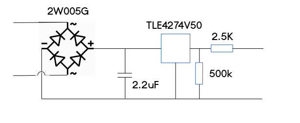
This would be a three part project: Make the Wall-O-Matic working and able to reliably send the pulses. Create an electronic circuit to transform the 25V ac pulses into something an ESP8266 could work with and finally convert the pulses into a format that allows us to play a song.
Part one was relatively easy. I carefully cleaned and adjusted all contacts and gave it a spritz of DeOxid. The digital scope confirmed that we had pulses. Here’s the problem: The 25V ac would of course fry any connected digital device. And the pulses are not only alternating current, but are also extremely dirty – based on the fact that a mechanical wiper arm passes over contacts resulting in spikes and sometimes even small sparks.

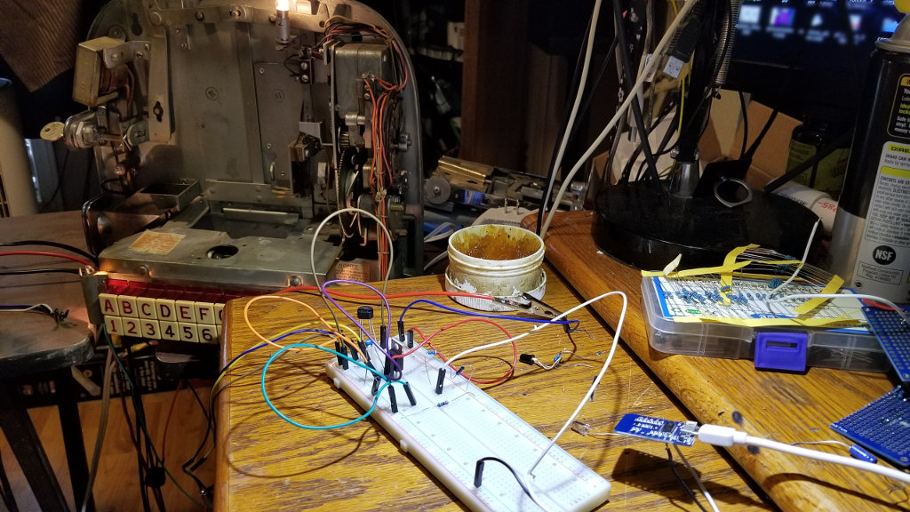
Other folks have solved this with more or less complicated converter circuits, I built and tested a more simple setup and hooked it up to an ESP8266. I tried and tried but couldn’t get a reliable decoding. Sometimes it worked flawlessly, other times the results were completely wrong. I revised my circuits to get a better signal, cleaned and re-adjusted the contacts and sometimes it seemed to have done the trick only to find out that, after a while, the pulse decoding went crazy again.

The Lumosur Arduino code is an environment that allows an ESP chip to be safely discovered, to communicate with the controller and to send and receive updates and messages. The modules for the Wall-O-Matic was based around “pulseIn” which basically blocks (with timeout) unless a pulse is detected and then returns the duration of the pulse. Because of the “dirty” signals, some verification was coded around to throw out bad (too short) pulses or spikes. It mostly worked. Sometimes. Other times, it did not work at all. I went crazy.
I can’t really tell how many times I revised and rewired the converter circuit and re-adjusted, cleaned the contacts in the Wall-O-Matic . I even replaced the ESP chip twice. It didn’t change a thing. I got valid responses at some times, complete junk at other times.
Finally it dawned on me. The ESP8266 was the problem.
And here is why: It’s operating system has to do a lot of tasks in parallel – especially with wireless networking. It’s a single core and the internal functions have preference over “normal” user code. So when it is busy doing WiFi communications or some other internal process, it can’t reliably service the “pulseIn” command and the result is faulty.
But how to deal with this?
I didn’t find a way to temporarily prioritize my code or block the system from doing it’s background stuff. I couldn’t port the Lumosur environment to an ESP32 on the fly and I didn’t want to install RTOS SDK.
The problem was haunting me in my dreams. I just wanted to get it done.
The pulses can come at any time. Once they have started, they have to be counted. Up to 21 pulses in the first group, interrupted by a gap or longer pulse, up to 5 pulses in the second group. Everything will be over in about 1.5 seconds.
So – how to get the ESP’s operating systems attention?
Of course. With an interrupt.
Now we are getting somewhere. An interrupt has priority over whatever the ESP is currently doing. All we have to do now is to hold on to that attention until the pulse is correctly timed.
while(digitalRead(Pin));
.. will do that. At least until the watchdog reboots the chip, but it’s perfectly OK for 40 or 50 milliseconds. Slap a few millis() around it to measure the time until the pin goes low and you’ve got yourself a reliable impulse counter.
attachInterrupt(digitalPinToInterrupt(GPIO_PULSE),wallboxIRQ,RISING);

void wallboxIRQ()
{
	unsigned long have,duration;
	have = millis();
	while(digitalRead(GPIO_PULSE));
	duration = millis() - have;
}
This is pretty much the basis for any reliable pulse counting on an ESP8266. It works flawlessly with now 100s of songs selected without any error. None.
The rest was easy. A script module was added to Lumoscript and the Wall-O-Matic was integrated into our environment.
#
# Wallbox
##############################################
begin wallbox
if [kitchen.wallbox.mode] > 0
  set [office.xjuke.play] = "queue://lumosur.local:8082/jukebox/[kitchen.wallbox.select].mp3"
end
There you have it. I almost found the limit of the ESP8266 chip. But some creative thinking made it possible to use even real-time pulse counting on this truly marvelous SOC.
Michaela Merz is an entrepreneur and first generation hacker. Her career started even before the Internet was available. She invented and developed a number of technologies now considered to be standard in modern web-environments. Among other things, she developed, founded, managed and sold Germany’s third largest Internet Online Service “germany.net” . She is very much active in the Internet business and enjoys “hacking” modern technologies like block chain, IoT and mobile-, voice- and web-based services.
Hallo Michaela
Hast du am Pulse-Counter noch weiter gearbeitet?
Ich wäre sehr interessiert an deiner Lösung, da ich für meine Wallbox 5220 etwas gleichartiges programmieren möchte.
Herzlichen Dnak für dein feedback.
Schöne Grüsse
Hi Michaela,
That’s a great project, I have recently restored a Rock-Ola Regis 200 and have a 1555 wallbox that I am going to connect to it via wifi so I don’t have to run a cable all around the house. It would be very interesting to see exactly how you decoded and captured the pulses from your wall box so would you share the code?
Kind Regards
Dave
As I have mentioned in my blog, the wallbox software has been incorporated into my Lumosur project and can’t be easily extracted. I will however send you a test software I used to try to pulse counting. It should get you going.
That would be very helpful – Thank you
I would love to have a peek at your entire code:) I seem to have the exact same seeburg wallbox and I’m using an ESP32 or 8266 to read the pulses then WIFI the result choice off to that handler. Pretty much exactly what you are doing, I think.
I am a novice at electronics (programmer for a living) and this is taking me a long long time.
I couldn’t get the rectifier working at the moment so I am trying an AC lightbulb and reading that with a photo diode.
Any help would be appreciated.
Follow up: I am having the same experience you seem to have had using pulsein. It works just enough to make it look like its the solution but then gives random bad results. I am now trying your interrupt method. I’m a week (or more:) into this and obsessed to wrap this up.
At the moment the pulses trigger the interrupt perfectly but the pin is reading LOW/0 for some reason.
As soon as the coffees ready, Ill be back at it 🙂
I will be hooking it up to a PC to play the music video’s or what ever interesting things the PC can do.
hello Michaëla
it would be great to have access to the code to transpose it on a rock ola wallbox.
Thanks in advance
PatLen
You could’ve simplified it a bit by realizing the “signal” is not 25vac, but is a supplied ground pulse, so 5vdc through a resistor would’ve given you a much better signal, through an opto-isolator would’ve been ideal
I have done similar with a Raspberry Pi, for ideas, see our group, my files and schematics are available there, and on github.
https://www.facebook.com/groups/1195286442029557