Building a Pool-Cooler from scratch
Every year, usually around July, we start complaining about the temperature of our pool. It’s simply neither refreshing nor fun to wade into water that feels like a bath tub. Time to do something about it …
I started to investigate pool chillers last year. There are heat pumps that can heat and cool (literally), there are compressor based units like air conditioners to chill the water and there’s (at least) one unit that uses evaporation to get the job done. Each system has its advantages and disadvantages – among other things, those power driven chillers like heat pumps or compressor units require quite some serious energy, with some pulling 5 Amps or more at 240 V. And .. those units are expensive too. Evaporation is of course not as effective as power driven units, but they require a lot less energy and .. I thought I could build one myself.
This is the story about building an evaporation pool chiller.
The story actually started a year ago with me procuring two 50 Gallon plastic drums. They were used to transport wine and one actually had about a Gallon left in it. It kinda smelled nice, but I didn’t had the guts to taste it. So I dumped some bleach into the drums and gave them a good clean. One of the drums ended up as a rain water storage for my garden, the other was earmarked for my pool chiller. I also purchase a 12V 10A power supply and a nice 12V fan last year, but I never got around to build the cooler.
When the pool temperature went about 92 degrees this year, I finally had the reason to start building the unit. How hard can it be? The water is sprayed on some medium, and runs of into the pool, a fan sucks the air out of the drum thus driving evaporation and the water is cooled. Others have built units before, so I had the general idea how it would look like.
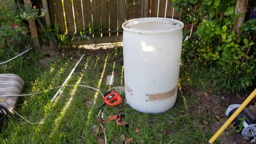
This is the basic design of my pool cooler to be. The bottom serves as a sump to collect the water, the slots allow air in which will be sucked through the wet medium to the top.
I designed a control environment with two DS18B20 one-wire temperature probes and an ESP8266 that would send the data to our in-home Lumosur IoT environment allowing us to conveniently verify the temperatures. The project was starting to look good …
The problems started when the family decided that the pool cooler should not be located in plain sight, but nicely tugged away in the little shed housing the pool pump. That required new thinking, because I couldn’t just use gravity to drain the water out of the sump into the pool, now I had to use a pump to return the water to the pool. Thankfully I already buried a second water line from the pool shed to the pool to drive a little water feature, I would simply re-purpose this line to become the outlet for my cooler pump. It would not be to much of a problem to do a little plastic plumbing to get the cooler into the pool system. So .. no problem?
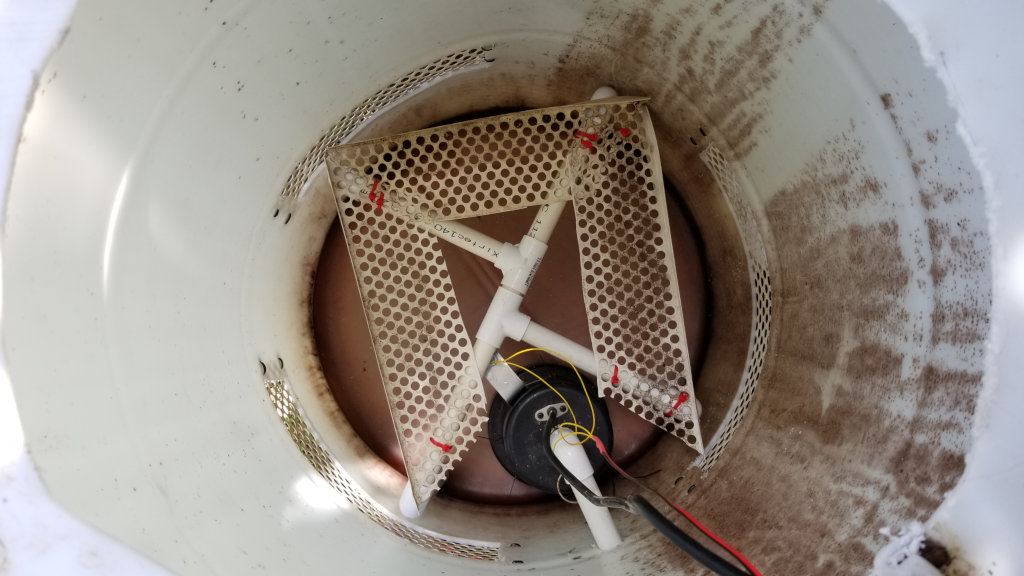
Top-down view into the cooler. The float switch is at the pumps 11 o’clock position. The contraption at the bottom separates the evaporation medium from the water collection sump.
Problem: The water sprayer is driven by the pool pump. The chilled water collects at the bottom of the drum and needs to be pumped out. This is what I call the “dependency” . I will mention the “d-word” quite a lot because imagine what happens when the sump pump doesn’t work? The pool pump will happily continue to pump water into the cooler, which will flood and turn our lawn into a wetland habitat.
Because its not easy or reliable to try to match the water inflow with the capacity of the pump, I needed some control mechanism to turn the pump on and off. In other words: Float switch. Some pumps come with an attached float switch but those require 2ft or more of water level to activate, I just have about 1ft to work with. Fortunately, I had a few left over float switches from a hydroponics system and I wired one (using low voltage from the ESP8266) and a 5V relay.
With the “dependency” in mind I opted for not controlling the pump relay from the ESP8266 – what would happen if it fails? If it hangs while waiting for a WiFi connection? Nope. I wired the relay and the float switch with only using the 5v power output from the ESP and gave it a try.
The sprayer started, driven by the pool pump, water collected in the sump and after a minute or so, the relay ticked on and the pump started draining the water. For two seconds or so as now the float switch had reached it’s “off” position and so the pump turned off. Only to turn on again as the water had risen just enough to turn the float switch on again. On-Off-On-Off .. in a two second interval. Clearly not a good idea.
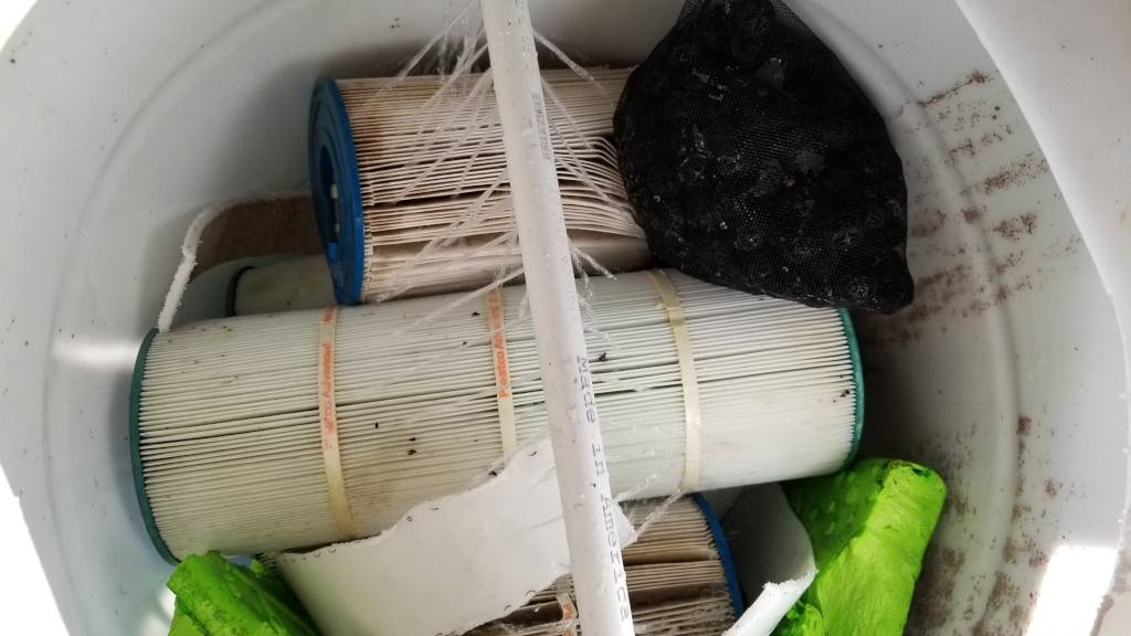
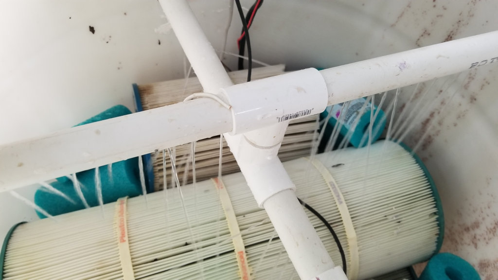
First test-drive of the sprayer. I use old pool filter cartridges as evaporation medium. Cutting one in half was tough work. Not recommended.
I evaluated technical solutions, thought about delay circuits, maybe even just a big electrolytic capacitor .. but in the end .. as soon as you start adding electronics you might as well just use what you have: an ESP8266 which has nothing to do (but measuring the temperature). I modified the source of my sketch to make sure that the ESP will always find time to check the status of the float switch, rewired it and it was ready for another test: This time with appropriate delays. And yes – this worked much, much better.
So .. my cooler had it’s air intakes cut out and covered (I didn’t build this thing so that toads can use it to enjoy themselves) the electronics was nicely tugged into a water proof box, the 12 V power supply delivered more than plenty to run the fan.
Time to get the cooler connected in to the pool system. It’s all PVC and getting it into the system shouldn’t be a problem.
Problem: While trying to get the cooler plumbed into my pool circulation, I broke one of the feeding pipes. Not only did I break it, I broke it in the very difficult position. The project was getting better and better.
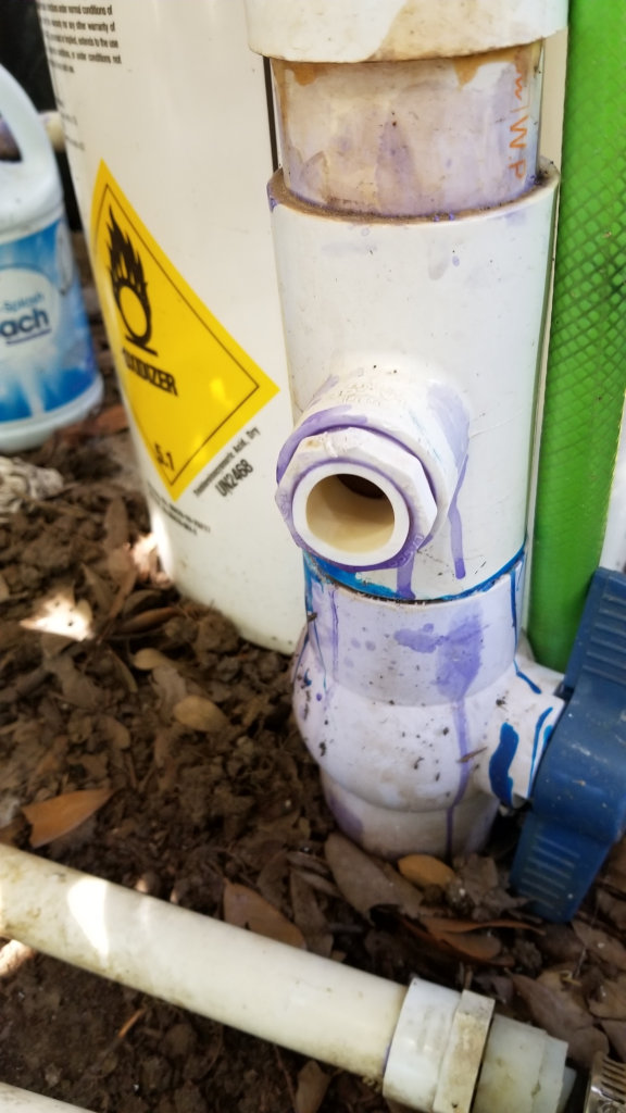
It took about two hours of painstaking work with a Dremel tool to carefully grind the old pipe stub out and to get a new pipe snugly fitted in.
But finally – everything was plumbed into the pool circulation. Time for a try. I ran an extension cord to the next GFCI outlet and let it run for a while. Always watching. Remember the “dependency” ? What if this 120 V GFCI outlet would trip ? No more pump action and the resulting wetland habitat. But it worked fine.
Only thing to do is to wire it into the pool electrical power supply. No problem.
Problem: No neutral. The pool was built before we purchased the home and the pool builders didn’t bother to run a neutral lead to the pool pump shed. F*ck me sideways.
The idea was to use the pool equipment double pole GFCI to protect the cooler system as well. If the cooler would fail, it would trip the GFCI and the pool equipment would be shutdown as well. Remember? The “dependency”?
The pool equipment consists of 3 devices: A timer, a UVC ozone generator and the pump. Silly me – I thought that the ozone generator was running on 120 V as it just draws a minuscule amount of power. Nope. It was powered by 240 Volts. Two hot leads, ground, but no neutral. Now – before you start thinking silly thoughts .. there are no shortcuts when it comes to water and electricity. No goofing around with using ground as a neutral “replacement”. I had to get a neutral lead into the pool shed.
The pool shed is just 15ft away from the main breaker panel. It would be easy to just run a neutral from there to the pump. But that is not allowed. A neutral lead has to run in the same conduit that houses the other wires.
Fish Tape time. It turned out not to be a big problem. Within an hour I had a neutral in the shed.
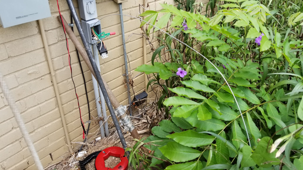
Fish-tailing the neutral through the correct conduit from the main breaker panel to the pool shed.
It took another hour to route the neutral (and the neutral return) to the double-pole GFCI panel and another hour or so to install an weather proof outlet. It measured 120 V. We’re good to go.
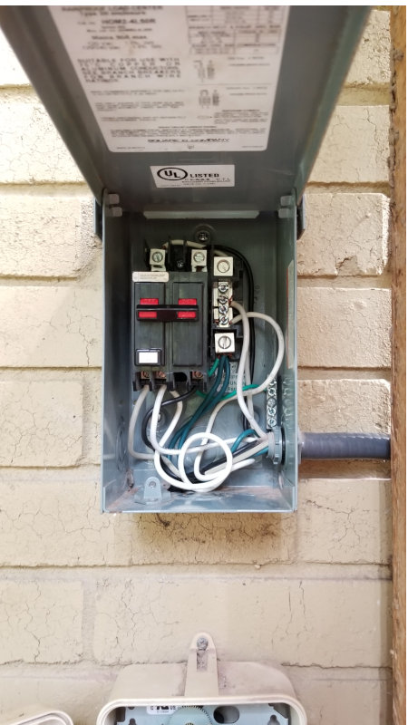
Problem: As soon as I plugged my system in, the double-pole GFCI tripped. First I thought it was my problem, but it wasn’t. Any device plugged into the new outlet tripped the GFCI. I went on “Stack Exchange” to ask for advise. Turned out the GFCI handled the situation correctly. What one has to do is to hook up the GFCI’s pig tail to the neutral bar (which runs all the way back to main breaker panel) and return the neutral from the designated neutral connector on the GFCI to the outlet. Now the GFCI can measure the current and knows not to trip if power is drawn from only one of the hot leads.
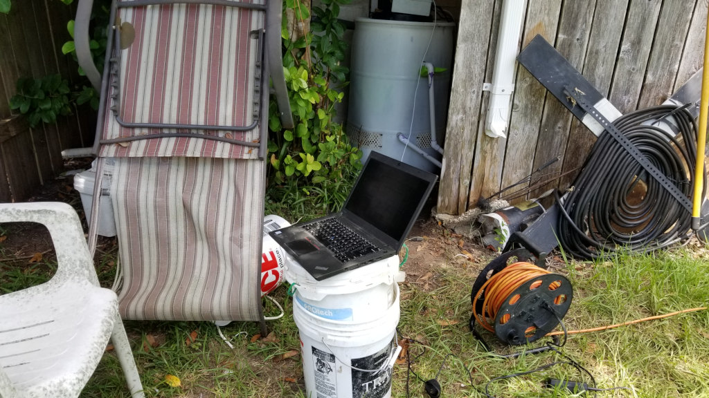
It took about 5 days to get the system built and now I was finally able to plug it in. And it worked. Sort of. Because there was no temperature reading on the terminal and water was splashing out of the vents in the bottom due to too much sprayer action.
I went to get the laptop to do some elective digital field surgery. But of course I didn’t have the Arduino IDE installed so I had to do this first. Next step: Get the .arduino directory with all my settings (and all libraries and sketches) from my work station. Bummer: the ssh_server wasn’t yet installed (new system) on the work station. So – after some unintended detours I was able to trace the error to a cold solder and fixed it.
Last minute surgery on the brains of the pool cooler. The common resistor for the Dallas 1-Wire temperature probes had come lose.
Next step: Taking care of the water splashing. I turned the power off, moved the fan to the side and installed some shields that direct the water spray away from the vents. But by now, the sump was overflowing because – you know – the “dependency” – no power to my system, no pump draining the sump. Easy fix: Turn system back on, pump comes alive, water is pumped out and I went back to adjusting the spray shields.
Until I smelled something odd. Like melting plastic odd. By moving the fan to the side, I had inadvertently blocked its movement and now I had a little smoke column coming out of its motor. That was the moment the pool-equipment GFCI tripped (yeah .. its working) and I was left with a blown power supply and a melted motor. Needless to say: I had fuses inline with the high voltage feeds into my system. And yes .. they too blew. But I didn’t have a fuse in the 12 V circuit relying on the power supplies “over current” and “short circuit” protection. Lesson learned. Obviously the power supply unit Chinese method of protection means it just shortens everything and rely on the circuit breaker (or in my case: The GFCI) to do the rest.
I didn’t like the idea of re-purposing a 12V car fan for my cooler anyway, because they put a lot of strain on the power supply and tend to run really hot. But I couldn’t find an outdoor rated fan in my required size (14″) so I went ahead and ordered a new power supply and a new 12V fan while the control box went into the lab for a new touch up changes.
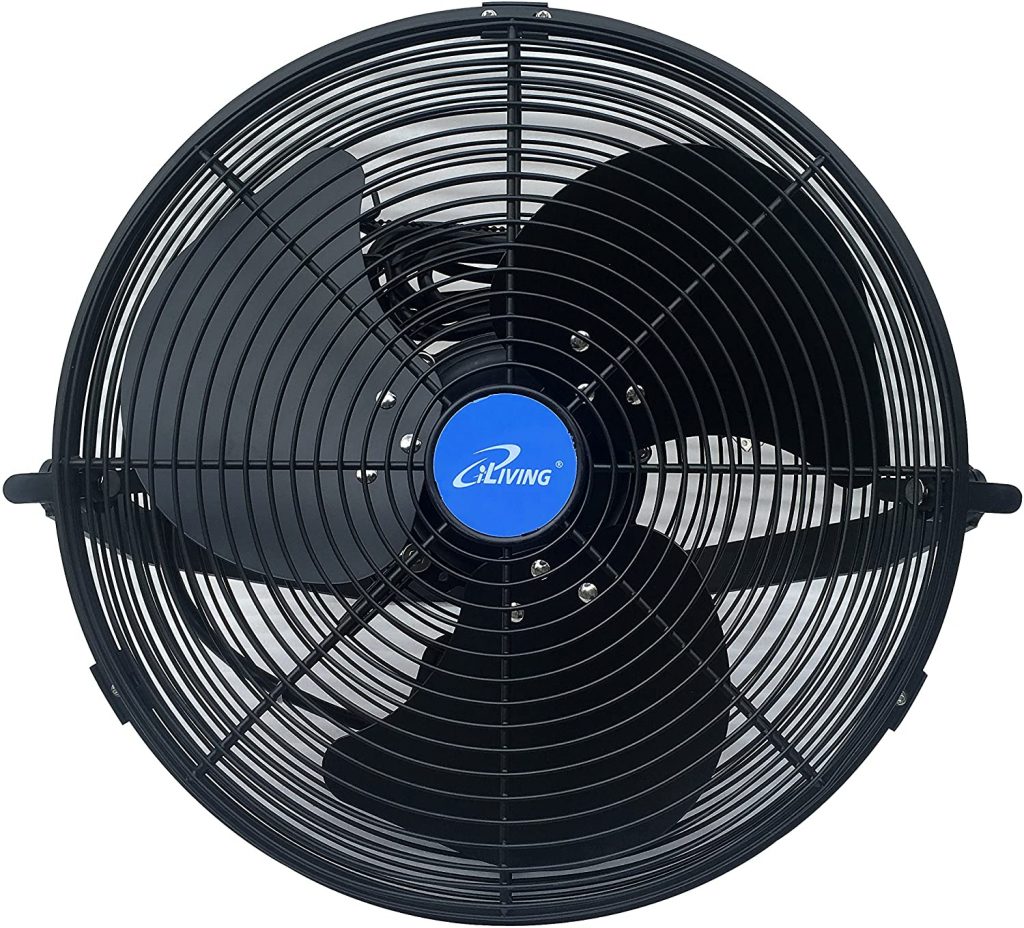
As things happen, I found a nice 120V fan (outdoor rated) with appropriate air moving volume (approx. 2000 cfm) and ordered it the very same evening and was counting the (4) days until it would be delivered. When I finally attached it to my cooler, I was happy, though I doubt it really delivers 2000 cfm. But it’s OK for the time being. It is also going to need a duct to reduce the side air flows, I am using a pool noodle for the time being.
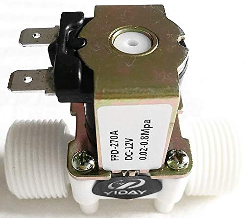
I also added a 12V electric solenoid valve and glued it into the water spray inlet. But that was a disappointment as it dramatically reduces the water pressure. I may have to cut it out again to verify why it is restricting the water flow as much as it does.
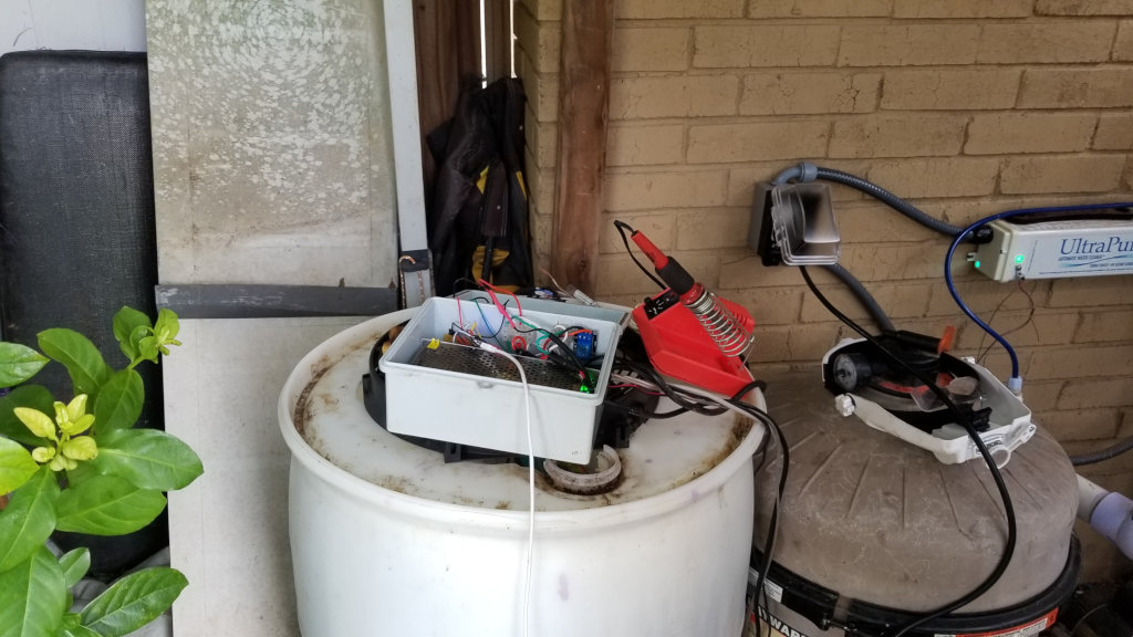
So – the cooler is finally doing its thing. Finally.
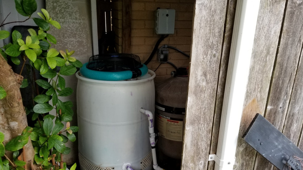
The DIY pool cooler is happily doing its thing in the pool shed.
Now .. for the big question: How well does it work?
That very much depends on the outside temperature and humidity. I am getting a temperature difference of between 3 and 5 degrees Fahrenheit in the current hot and very humid environment (tropical storm Hanna is on the way). I have seen as much as 14 degree F difference during less humid conditions. So – I’ll have to see if it makes a dent in the overall pool temperature. But every little thing helps 😀
A quick calculation:
$ 20 —– 50 Gallon Drum
$ 99 —– Outdoor rated fan
$100 —– Sensors, Enclosure, ESP8266, Relay
$ 60 —– Motorized ball valve (not strictly necessary)
$ 50 —– Miscellaneous items
$ 269 Dollars Grand Total ($329 with ball valve)
And a lot of experience gained. It was a fun (though at times frustrating) project.
UPDATES:
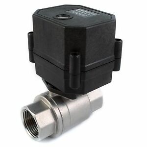
As mentioned above, I wasn’t happy with the solenoid valve because it just removes too much pressure. I also learned that those valves are not really meant to be active for hours at a time. They get hot and their lifespan will be short. Thankfully I found a helpful seller “valves4projects” on Ebay and they suggested to use a motorized ball valve. I had considered this before, but didn’t know that there are actually valves that can close themselves when power is disconnected. Well .. they pointed out a specific valve and it works beautifully. Full pressure in the system and it closes automatically when power is lost (or disconnected).
I also changed the configuration of the sprayers. I started with one pipe across but it was difficult to drill the holes so that the water would be distributed evenly. I have now two pipes which allows me to get the water where I want it to be.
The new sprayer configuration with two pipes.
We haven’t had a sunny day since the pool cooler has been ready. As a matter of fact, the cool rain water can clearly been seen on the units temperature plot. But at least I am able to adjust the water pressure and flow now and can direct the sprayers to get the maximum cooling effect.
UPDATES (2)
Though the pool cooler is cooling, I never got more than 2 or 3 degrees of temperature difference out of it. A little more was possible by reducing the flow, but that was not really an option. So I investigated alternative filling materials. After some research I realized that the combination of water distribution (in the media) and air flow has the most impact. Commercial operators use elaborate style of corrugated plastic and I contacted several companies trying to get a few samples I could use for my cooler – most didn’t even bother to answer.
Anyway – I am currently trying a different approach. I am using vinyl fencing material rolled and sized to fit into my cooler.
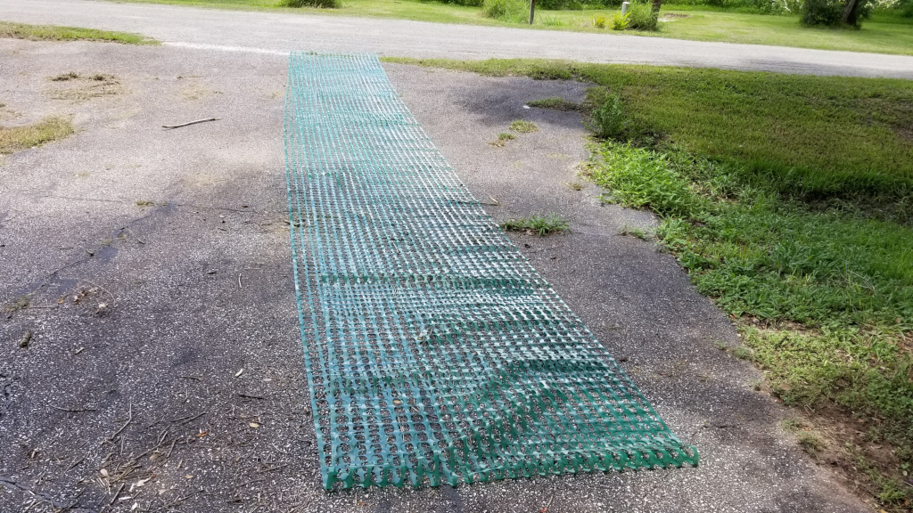
This is about 50 yards of vinyl fencing material getting ready to be rolled up as pool cooler evaporation material.
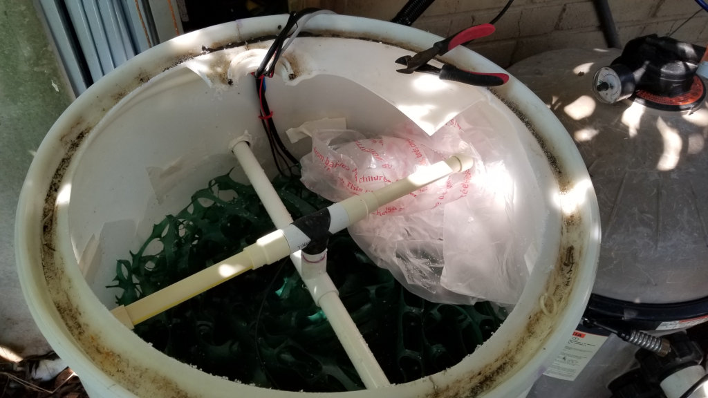
It was a bit tricky to get it rolled just right, not too tight and not to lose, not too large, not too thick. It was also a challenge to keep debris out of it. But I managed to get it into the pool cooler just fine.
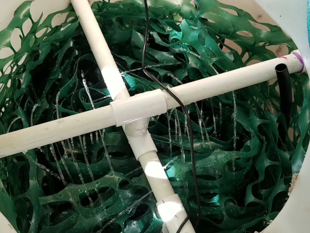
The DIY pool cooler with new filler material.
This seems to work much better. It distributes the water nicely and doesn’t inhibit the air flow very much. I am now getting about 7 degrees of temperature difference on a bright sunny afternoon (91 degrees, 63% humidity) with a decent flow of water.
I will also change the sprayer somewhat and ordered small drill bits (0.8mm) . Yes – I ordered a number of ’em well knowing that they break very easily. I will keep the blog updated.
UPDATES (3)
Though I went ahead with the smaller holes, it didn’t really make a big difference. The only reliable way to get water distributed correctly would be a rotating arm. But how would one do that? Turns out – it’s not really complicated. But I needed a few tries.

Now with the new rotation arm supplying water everywhere – it was splashing out of the bottom vent holes. Big time.
I tried different methods of re-directing the water from the vents, but nothing worked reliably. Finally I ran a garden hose along the inner circumference to act as a distance holder, than installed plastic splash curtains that extend about an inch over the bottom vents (the garden hose keeps it about 1/2″ away from the wall.
Finally I installed a big new 20″ fan. I call it “the beast”. The old 14″ fan is going to help me stay cool on the porch. In order to accommodate “the beast” I had to cut open the top.
Cutting away the top to fit in “the beast”. No – not with the pliers, I used a reciprocating saw for that.
But the beast tried hard to start – it just didn’t get enough air. I completely disassembled the cooler again, extended all the lower air vents a bit, added a few more inches of “breathing room” and “the beast” was finally happy.
The pool cooler with rotating feeder arms and “the beast” doing its thing on top.
So .. there you have it. The evaporation pool cooler version 1.0 is ready. Finally. Ready. It currently delivers a steady 11 degrees of cooling temperature with an unimproved filler medium (at 81 F, 80% humidity) . Thankfully – and with the help of the friendly folks at CoolingTowerDepot – my cooler will get professional grade cross fluted fill material. This is serious stuff that not only splits the water 8 times per 12″ section, it may also increase the air flow compared to my rather rough filler material.
UPDATES (4)
The professional cross fluted fill material arrived and was installed in the cooler. The material is a light-weight plastics that is easy and hard to work with at the same time. I cut it into shape with a sharp knife, but took a few bleeding cuts from the sharp edges of the plastics before putting on gloves.
You have been warned.
The new filler material made some, but not a dramatic lot of difference. There’s probably just not enough room in the small tower to get any more temperature difference regardless of the filler medium. Though I was able to increase the water flow somewhat while keeping the same 10 to 12 (depending on the humidity of the air) degrees of cooling, the material is perfect for stacking so I am already contemplating to increase the height of my tower to be able to fit a second layer of filler material. Not sure when I am able to get to it though.
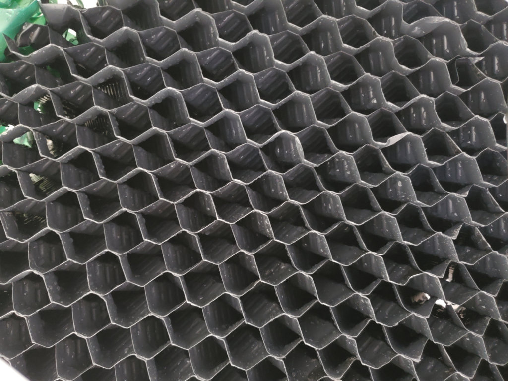
I also had to address an additional problem I should have dealt with in the beginning: Water splashing out of the louvers. I finally took the time to fix it for good – with plastic “reflectors” extending a bit over the louvers and silicone’d so that no water can get behind. That did the trick and no more water is lost due to splashing.
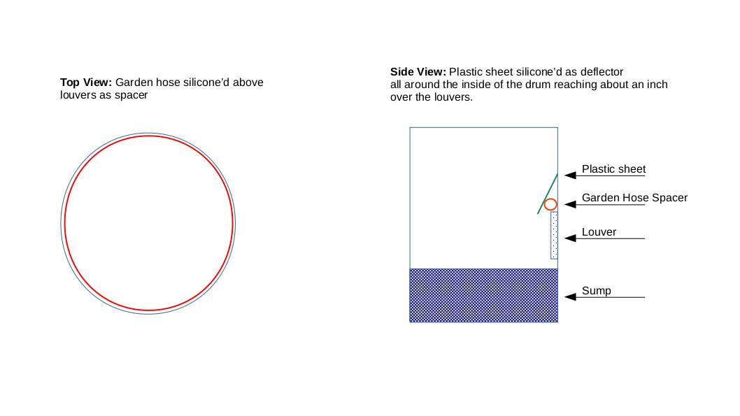
Schematic of the plastic water deflectors with a garden hose as spacer. Make sure to use a good marine-grade adhesive sealant.
Another issue you should be aware of is evaporation. Well – it’s an evaporative cooler so yes – you will lose water in your pool. But there are steps to reduce the amount of water loss.
I got some stainless steel mesh netting from Amazon and spanned it between the water sprinklers and the fan. And sure enough, water droplets form at the mesh and drip down into the cooler. I am sure this will significantly reduce the amount of water loss, but running the cooler will make the pool lose water. So you need to keep an eye on your water level.
As it stands today, the combination of a small sun shade sail and the pool cooler running at night keeps the pool at a very comfortable and refreshing 83 degrees, even through an ongoing hot spell with average daily temperatures of around 94 degrees and non-stop sun baking. This not only makes the pool very enjoyable, it also cuts down on chemicals.
Mission accomplished. I’ll keep you posted.
Michaela Merz is an entrepreneur and first generation hacker. Her career started even before the Internet was available. She invented and developed a number of technologies now considered to be standard in modern web-environments. Among other things, she developed, founded, managed and sold Germany’s third largest Internet Online Service “germany.net” . She owns a music production business but still very much enjoys “hacking” modern technologies like block chain, IoT and mobile-, voice- and web-based services.
UPDATES (3)