Measuring power, voltage and current with an ESP8266
There are a few ways to measure power consumption, voltage or current with an Arduino. Unfortunately, the ESP8266 has a few limitations that make it somewhat difficulty to get things going. Let’s look at an easy way to achieve our task.
It’s not complicated to hook-up the very clever ASC712 current sensor module to an Arduino. However, the ESP requires a bit more soldering. Among other problems, the sensors needs 5V while ESPs only like around 3V and the ASC712 output delivers 0V – 5V, with 2.5V at 0 Amps flowing. Unfortunately, the ESP can only measure 0-1 V – in other words, you’ll need additional circuitry. But you need even more – power supplies, a case – you get the idea.

Let’s have a look at the HLW8012 chip. It measures voltage, current and even power – though it delivers its results in an unusual way. It pulses it’s output and the frequency increases as the values increase. But that we can handle with our ESP chip. Don’t grab the soldering iron just yet, because you can get a complete package, including power supply, case and the whole thing around at for about $7 or less.
The KMC 70011 “smart plug” comes with everything you need to switch your power on or off, to measure the voltage, current and even the power. But here’s the catch: You can not use any serial connection while the plug is connected to the power line. The measuring circuit is not isolated and it will zap you, your serial converter, your computer. I am speaking from experience. Don’t do it. Find other ways to debug. Maybe this remote debugging tool ?
Anyway – the KMC “smart” plug works nicely and gives pretty stable results. Here’s what you need to know if you want to start hacking: 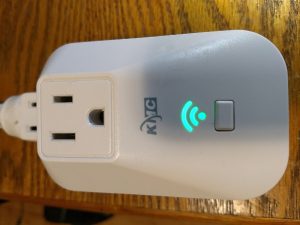
Relay on GPIO14
Button on GPIO 0
LED on GPIO 13
HW8012 Select on GPIO12
HW8012 CF1 on GPIO 5
HW8012 CF on GPIO 4
But wait, there’s more. The current shunt seems to be at around 0.0025 Ohm and the voltage divider circuit clocks in at around 2.2KOhm. Those values give me between 118 and 122 Volts and a 1500 Watts room heater shows between 1495W and 1502W on the dial. That’s close enough for me. Here is a link to get you started: ESP library for Sonfoff POW
So – what can you do with that? You could keep taps on your power consumption. But that’s boring – especially if you could use the info to do some smart stuff. Like slaving other devices – e.g. turn on the popcorn machine when the switch senses power to the TV. Seriously – You turn on the TV with your remote, the circuit senses the power draw and turns the amp on or kills the light. A “smart” environment needs to be able to gather all sorts of information. This little device makes it easy to extend our reach into the home power environment.
UPDATE [September 1st, 2018]: The sensor has difficulties reading very low power devices, like e.g. electronic devices in “Standby” mode. Though it correctly shows 0 Watts most of the time, it also spikes to 5 Watts or even 10 Watts for one reading cycle. This is bad if you use the device to “slave” other devices to it’s power readings. I added a verification function that ignores a cycle if it reads larger that 25% of the previous reading. In other words – a power level change is triggered only if two following cycles are roughly the same. This seems to be working quite well.
UPDATE [September 7th, 2018] We’ve been asked to check the new(er) ? versions of the KMC 70011C “smart” plug. It comes with an TYWE3S chip that replaces the ESP8266. But – no worries. The new chip is fully ESP compatible, has the same pin-layout and works fine with an Arduino environment. And yes – we verified it. Enjoy.
About the author:
Michaela Merz is an entrepreneur and first generation hacker. Her career started even before the Internet was available. She invented and developed a number of technologies now considered to be standard in modern web-environments. Among other things, she developed, founded, managed and sold Germany’s third largest Internet Online Service “germany.net” . She is very much active in the Internet business and enjoys “hacking” modern technologies like block chain, IoT and mobile-, voice- and web-based services.
Howdy from another S. Tx pilot! And thanks for the posts. Search brought me to them while I was looking for information on flashing the KMC 70011. I succeeded, in part, thanks to your posts.
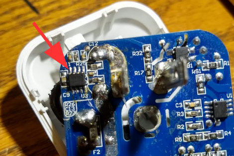
BUT… (always one, right?) I broke the power supply inductor on one of my units while putting it into my vice. It is labeled “L1” and has rings of “brown, brown, red”. I have not been able to find circuit diagrams online and don’t have a way to test the L1 value on another unit. Do you know the value of L1 so I can fix this one? I know, it’s just $12. I’m silly like that.
Nope, sorry. The units I broke I threw away. Are you talking about the resistor in the top right corner? It kind of looks like brown red red to me, which would indicate a 1.2KOhm resistor. Brown Brown Red is 1.1KOhm .. so I think both would work.